

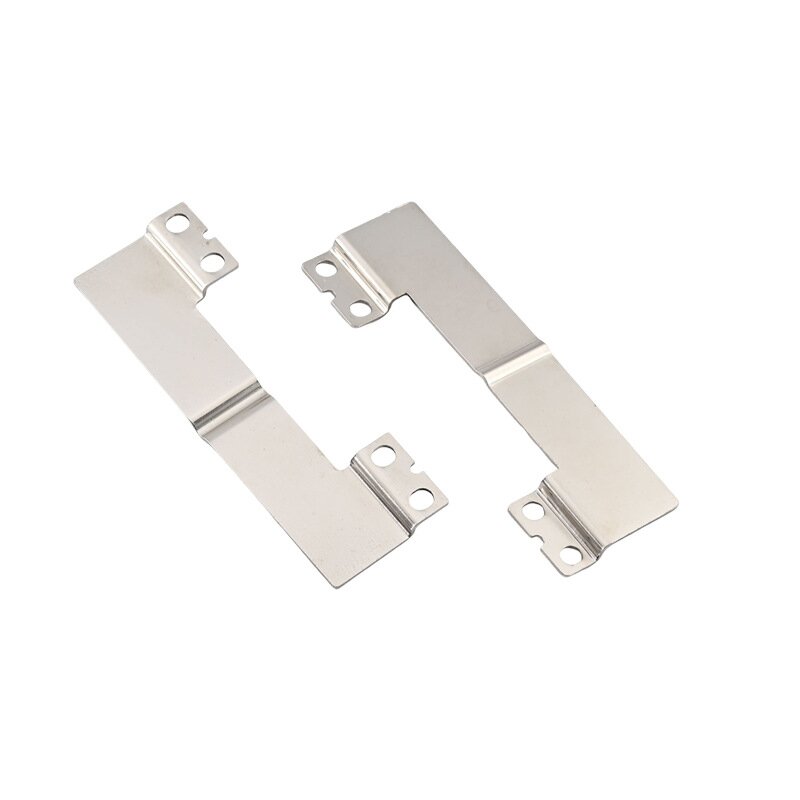
A deep-drawn part looks straightforward in CAD. The drawing is simple: a cup, a can, a housing. Then the tool is cut, the first samples run, and the problems appear—wrinkles on the flange, a tear near the punch radius, or an uneven rim that no trimming allowance seems to fix.
The root cause is rarely the press operator. It is almost always a design decision made months earlier, before the tooling was released. Three decisions determine whether a deep-drawn part runs reliably or drains engineering hours: whether deep drawing is the right process, how the geometry and material interact, and whether features are positioned for material flow rather than against it.
Decision 1: Confirm deep drawing is the correct process
Deep drawing pulls a flat blank into a die cavity under controlled blank-holder pressure, producing a seamless hollow shell. Stamping, by contrast, primarily cuts and bends flat stock in-plane. The dividing line is depth relative to opening size. Deep drawing becomes the stronger candidate when the depth-to-diameter ratio exceeds roughly 0.8; for enclosures requiring a depth-to-width ratio above 1.5, multiple draw stations with intermediate annealing are usually necessary.
The cost structure differs accordingly. Deep drawing tooling is typically higher—multi-die sets commonly fall in the $30,000–$80,000 range, compared with $15,000–$50,000 for a progressive stamping die—because the tooling must control radial material flow, not just shear and bend. That investment only makes sense when the part geometry truly requires a seamless, deep shell and production volume is sufficient to amortize the tool across the order.
If the part is shallow, has complex in-plane cutouts, or the annual volume is modest, stamping or a hybrid sheet-metal-and-weld approach will usually deliver a lower total cost. A deep-drawing quote that ignores this comparison is not a fair quote—it is a future cost overrun.
Decision 2: Treat geometry and material as one system
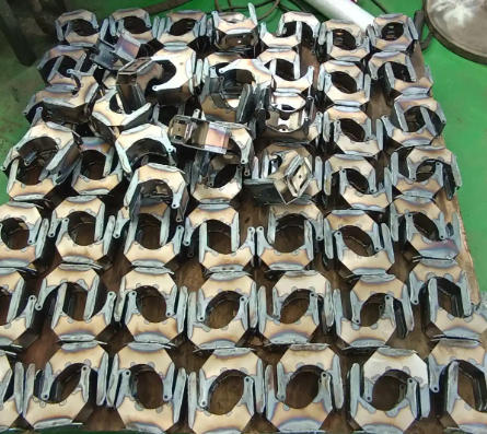
Once deep drawing is confirmed, the single most consequential geometric value is the punch radius. A radius that is too small concentrates strain at the point where the sheet turns into the wall and raises the risk of splitting. The die-entry radius must simultaneously allow smooth blank flow without releasing control of the flange. In practice, corner radii below 3× material thickness are high-risk for stress-concentration cracking; 5× thickness or greater is the safer design target.
Wall thickness will not remain the nominal gauge. The bottom of a deep-drawn enclosure typically thins by 5–15% under tensile stretching, while the flange area thickens by 5–10% under compressive radial stress. Specifying a minimum thickness only where the function demands it—rather than uniformly across the part—prevents the design from becoming unnecessarily difficult to form.
Material selection is equally decisive. Low-carbon drawing steel offers the widest forming window. Stainless steel brings corrosion resistance but work-hardens rapidly, so multi-draw sequences may require intermediate annealing. Aluminum formability varies sharply by alloy: 5052-O and 3003-O draw successfully, while 6061-T6 is generally too rigid for deep drawing and belongs in stamped or machined applications. Specifying “aluminum” without grade and temper is a common source of first-article failure.
Decision 3: Place features around material flow, not across it
Holes, slots, and embosses interrupt the radial flow of material into the die. A hole pierced before drawing will stretch, distort, or shift—especially near a corner or the punch radius. The practical rule is to produce critical openings after drawing, then use laser cutting or CNC machining only where IT7–IT8 tolerances are required.
The blank holder deserves the same attention. Too little force allows flange wrinkling; too much restraint causes tearing near the punch radius. Draw beads add local control when different regions of the blank feed at unequal rates, but they must be designed alongside the part geometry, not added as a press-side correction.
A design review that asks three questions before tooling approval catches most preventable failures: How many forming stages will this geometry require? Which features will be formed, trimmed, or machined after drawing? Is intermediate annealing or final calibration part of the sequence? These are not questions to answer after the first samples fail.
Shenzhen Hony Tai provides deep drawing, metal stamping, sheet metal fabrication, and precision machining under one roof. We review customer drawings for forming feasibility before quoting, so the process and tooling sequence are matched to the part—not forced onto it. If you have a deep-drawn component moving toward tooling, send the drawing and target volume. We will return a manufacturability assessment and a process-based quote, not a guess.