
Most stamping projects fail before the first part is ever produced—not on the press, but in the gap between a CAD drawing and a manufacturable die. The buyers who get predictable cost, quality, and lead time are the ones who close that gap early.
This guide walks through the decisions that actually determine whether a custom stamped component ships on spec and on schedule, from tooling selection through DFM review, defect prevention, and final inspection.
Tooling First: Match the Die to the Part, Not the Other Way Around
The die type sets the tooling budget, the lead time, and the per-part cost curve. Getting this decision right at the RFQ stage is more valuable than negotiating a few cents off the piece price.
Progressive dies are the workhorse for high-volume flat or shallow parts with multiple features produced per stroke. Tooling lead time typically runs 4–8 weeks for a new die, and longer for complex multi-station designs. Once volume is confirmed, progressive tooling amortizes quickly—but the upfront investment is three to five times that of a single deep-draw tool for a comparable medium part.
Deep drawing is the correct process when the part is a hollow shell—a housing, sleeve, or cup—with a depth greater than roughly half its diameter. A one-stage draw tool is simpler and faster to build than a progressive die; a multi-stage draw adds tooling complexity but becomes necessary when geometry exceeds the forming limits of a single draw.
The practical rule for buyers: do not lock in a progressive die until annual volume and part geometry both justify it. A supplier with in-house tooling capability can usually tell within days whether the part is a one-stage draw, a multi-stage draw, or progressive-die work—before quoting.
DFM Is Where Tooling Cost Is Won or Lost
Design for Manufacturability is not a courtesy review. It is the single highest-leverage step in the tooling-to-parts chain. Proper DFM reduces tooling cost and minimizes scrap, and it protects quality consistency across millions of cycles.
Two failures recur in custom stamping RFQs.
The first is unrealistic tolerances. Stamping is a high-speed forming process, not machining. Delivering very tight tolerances consistently, for thousands or millions of parts, via stamping is nearly impossible. For most functional brackets and housings, ISO 2768-m general tolerances are entirely sufficient; bend angles typically sit between ±0.5° and ±1.0° because springback and forming control limit tighter capability. A hairline on a screen is not a tolerance.
The second is feature geometry that fights the die. A slot that is difficult to punch without tearing, or a hole placed too close to a bend, will drive tool maintenance and scrap for the life of the program. A slightly wider band, an emboss, or a hole moved farther from a bend can prevent wrinkling, tearing, cracking, or springback—often with no functional compromise.
This is why the most effective stamping suppliers ask a simple question before reviewing the drawing: What does this part actually do? A lance-form slot intended for a zip-tie attachment, for example, can be redesigned to punch earlier in the die, coined to smooth sharp edges, and formed with a less-severe radius—producing a better part and a more stable tool simultaneously.
Deep Drawing: Control the Process Parameters, Not Just the Die
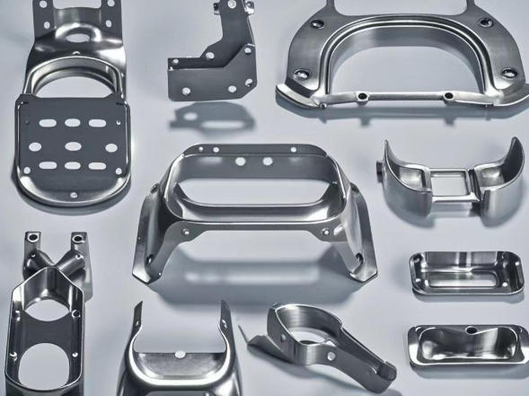
Deep drawing carries a distinct defect profile: wrinkling, tearing, and excessive thinning are the common failure modes, and they trace back to process parameters rather than die geometry alone.
Blank holder force is the primary lever. Too little, and the flange wrinkles from excessive compressive stress; too much, and the material fractures. Die clearance, stamping speed, and friction coefficient all interact with blank holder force, which is why simulation-driven parameter optimization matters on parts with meaningful draw depth.
Finite element simulation allows a stamper to run the draw before cutting steel. On flanged cylindrical parts, response surface optimization of blank holder force, stamping speed, friction coefficient, and die clearance has been shown to reduce the maximum thinning rate measurably—improving forming quality without changing the tool design. For buyers, the takeaway is practical: ask whether your deep-drawn RFQ will be simulated against the proposed die before tooling is released. A supplier that skips this step is transferring forming risk to your production run.
From First Article to Finished Parts: Inspection That Closes the Loop
A stamped part is only conforming if it matches the drawing on the dimensions that matter. General dimensions default to ISO 2768 or ANSI Y14.5, with DIN 6930 specifically applicable to stamped parts. Burr height should be called out explicitly—a target of ≤ 0.05 mm is a reasonable default for many precision applications—along with edge breaks, which fall outside ISO 2768 scope and must be specified separately.
The practical inspection sequence for custom stamping runs from incoming material verification through in-process checks to final dimensional and visual inspection. Critical-to-function dimensions—datums, mating interfaces, and any feature that governs assembly—belong on the control plan from the first article onward, not as an afterthought at final inspection. A supplier that reviews part geometry, revision, dimensions, datums, forms, and interfaces as part of the RFQ is already building that control plan into the quote.
What to Send in a Stamping RFQ
A DFM-ready RFQ is not a long document. It is a complete one. The inputs that most directly determine tooling feasibility and cost are: a controlled 2D drawing with tolerances; a 3D CAD file (STEP or IGES) where available; material grade, temper, and thickness; surface finish or coating; and annual volume with batch size.
Material specification matters more than most buyers expect. Grade, temper, and thickness drive press tonnage, springback behavior, and tool wear—generic material names are not enough to quote a die responsibly.
Shenzhen Hony Tai works from customer drawings and samples across metal stamping, deep drawing, sheet metal fabrication, and precision mechanical machining. We review the drawing for DFM before quoting, simulate draw-intensive parts where the geometry warrants it, and control precision and production quality from tooling through finished parts—with stable delivery and cost-effective solutions for global clients.
Have a drawing ready for tooling review? Send your 2D drawing, 3D model, material spec, and annual volume. We will return a DFM-oriented quote and flag any feature that will drive tool cost or defect risk—before you commit to a die.